Series Board Connection Diagram
There are two basic ways in which to connect more than two circuit components: In the below diagram, we made a circuit for glowing led on a breadboard.

Block Diagram Circuit Wiring Diagram
It is very easy to download any file from this site.
Series board connection diagram. Hello folks,our video about!simple and easy way to solve your basic problems with full of confidentby learn with skilled folk, we can save our time as well a. Conceptdraw is a fast way to draw: A schematics diagram is a pdf file that is designed by drawing type, you can see every component easily and details of everything in a diagram.
What is the 5 pin relay wiring diagram and how to use 5 pin relay? To make or wire the complete series board fist of all connect the phase line wire to the socket outlet terminals and then connect the one way switch. So overall it makes a repair very easy.
1978 x 2560 pixels file type : How to make series testing board for low resistance appliances testing. Here, we have three resistors (labeled r 1, r 2, and r 3) connected in a long.
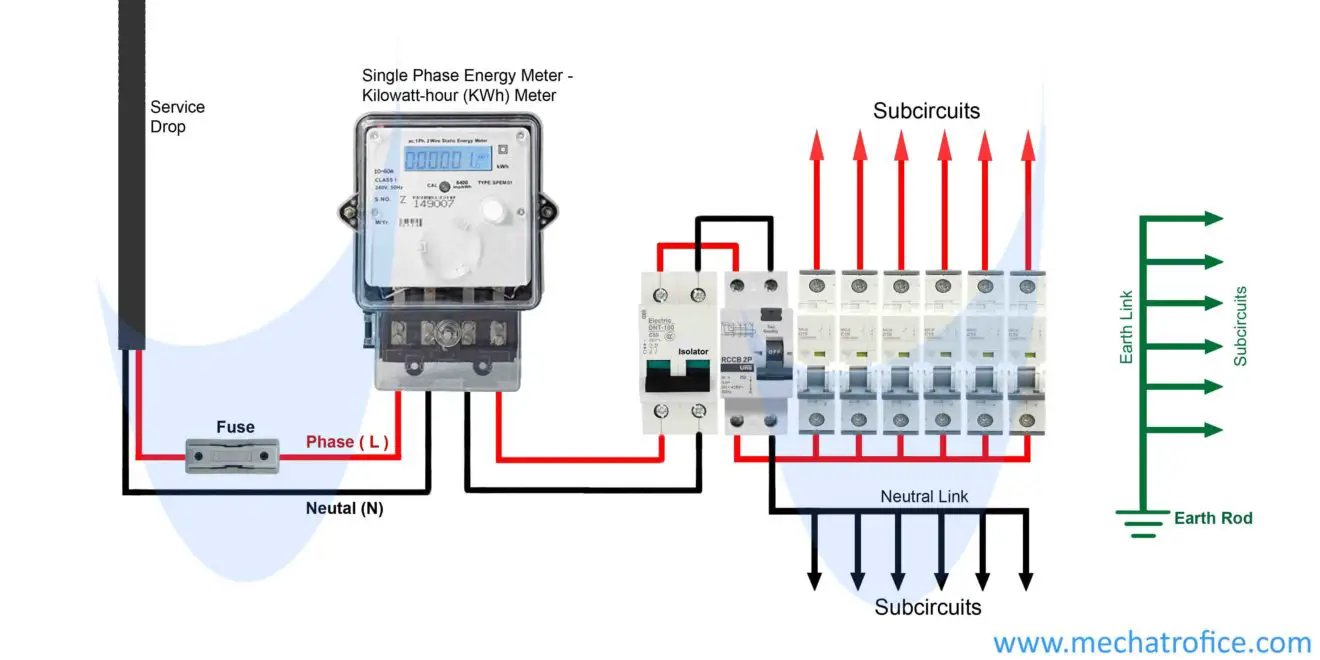
Keep an eye out of common mistakes like mixing ground and supply, connect in a wrong rail, ics not set properly, etc. In the above wiring diagram, we have connected a 63a fuse in series with the main input phase supply. Series board kya hai , series connection , series diagram testing electric product,
So 63a is enough for this switchboard. One must still make certain that the source voltage will match the voltage rating of the windings, and the secondary voltages will match. Tech advice #seriestestingborad connection diagram and making board urdu/hindihello fiends welcome to our channel so guys in this video i going to show that.
Thus, when a number of resistors are connected in series, the effective resistance (total resistance in the circuit) is gotten by adding. Keep in mind that the connection diagram on the transformer nameplate will provide the necessary wiring information to make the proper series or parallel connections. First, an example of a series circuit:
Like,share, comments,and suscribe my channel. A series circuit is a circuit in which resistors or loads are connected end to end so that the circuit will have only one path through which electric current flows. Series board connection is important.you see vedio after connection.
Series board connection diagram boat wiring for dummies manual image size : The diagram above is the 5 pin relay wiring diagram. Using these diagrams you can easily find your faults in your acer laptop motherboard.
Brake controller wiring diagram series board connection diagram image size : 198 kb 6 wire trailer plug gallery In this diagram, the total load of the circuit is 56a(calculated by the total of all switches ratings).
This is how a relay is wired commonly. Electric test series board wiring connection and diagram. 21 pictures file size :
2550 x 3300 pixels file type : In many places where we have not a multimeter and we required to test electric motor or other connectivity test then we can use series testing. George patrick shultz, in transformers and motors, 1989.
Electrical circuit diagrams, schematics, electrical wiring, circuit schematics,. Electric test series board wiring connection and diagram.thanks for watching video. My this post is about the series testing board which we can use in those places where we did not available other electrical testing device.it is the oldest but one of the best method of testing electric appliances or devices.
Series parallel testing board circuit diagram magic.
Help for Understanding Simple Home Electrical Wiring Diagrams

Wiring Diagram To Sensor Flood Light Wiring Diagram

How to Make Series parallel Electrical Testing Board (In

WiringDiagramForFlueDamper RAUR.US

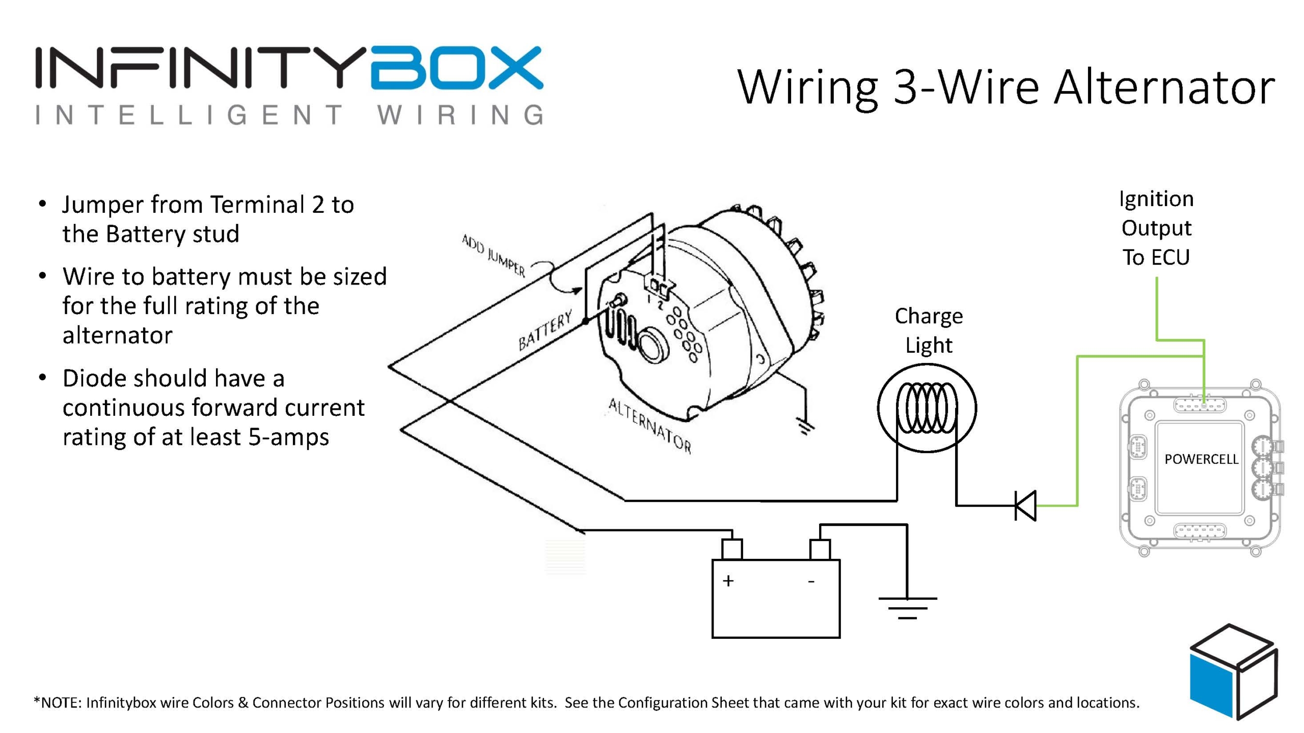
Alternator Upgrade Wiring Diagram Irish Connections

Series testing board क्या है, कैसे बनाये, कनेक्शन डायग्राम

How to Make Series parallel Electrical Testing Board (In

electric board circuit diagram Wiring Diagram

electric board circuit diagram Wiring Diagram

electric board circuit diagram Wiring Diagram
electric board circuit diagram Wiring Diagram

OnboardBatteryChargerWiringDiagram RAUR.US

PhysicalDatumWiringDiagram RAUR.US

Wiring Diagram To Sensor Flood Light Wiring Diagram

Single Phase Wiring Diagram Symbols Wiring Diagram

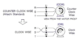
45 3 phase ac compressor wiring diagram Wiring Diagram

OnboardBatteryChargerWiringDiagram RAUR.US

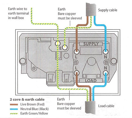
how to wire an electric cooker wiring diagram Wiring Diagram


